The digitalSTROM driver is an invisible server component with the Ability To control digitalSTROM Installations. The Driver connects to the digitalSTROM server. This serves as a Data Point Supplier and Interface to the System.
The available Zones, Groups and Devices are read in. The System must be Put into Operation in advance via the Manufacturer's Software.
Data points of the component
Name |
Type |
Function |
|---|---|---|
Diagnosis [Text] |
Output |
Warning: Diagnosis or Debug-Outputs are only intended for the Event of an Error. Please use only with Consultation with the Support Team! These can significantly affect the Service's Performance when Used. |
Advanced Diagnosis |
Bidirectional |
The Output of the Diagnosis can be expanded here with an to value. |
Event Expenses |
Output |
This is where the Answer to a sent Command is issued. The Output is used for Diagnosis in the event of Miscircuits. |
Update device values (Bus Query, slow) |
Input |
A One-signal at this Input starts updating the Values from the Devices. |
Update meters (Bus Query, slow) |
Input |
A One-signal at this input starts updating the Consumption. |
Meter Update Interval (Bus Query, slow) |
Bidirectional |
In the set Time Interval, the current meter values (selected in the Channel editor) are read out of the Device (0 = disabled). As this is done via the Bus, the individual Queries take a very long time. This Option should only be used if reading out of the Server is not enough. |
Sensor Update Interval (Bus Query, slow) |
Bidirectional |
In the set Time Interval, the current sensor values (selected in the Channel editor) are read out of the Device (0 = disabled). As this is done via the Bus, the individual Queries take a very long time. This Option should only be used if reading out of the Server is not enough. |
Update sensors (Bus Query, slow) |
Input |
Trigger to read the current Values of the Devices via the bus (0 = disabled). |
Update sensor/meters (Bus Query, slow) |
Input |
Trigger to read the current Values of the Devices via the bus (0 = disabled). |
Update sensor/meter (Server) |
Input |
Trigger to read the current Values of the Devices from the Server (0 = disabled). |
Sensor/meter Update Interval (Server request) [s] |
Bidirectional |
In the set Time Interval, the current consumption values of the Devices are read out of the Server (0 = disabled). |
Update Scene Names |
Input |
A One-signal at this Entrance starts updating the Scene names. |
Update Scene Values (Bus Query, slow) |
Input |
A One-signal at this Input Starts updating the Scene values. |
Delete Scene values |
Input |
Deletes All internally stored Scene values. The EisBaer stores the Values of the Devices for each scene called to reduce the bus load. If The Scenes are Changed, either the Scene must be queried, or the Scene must be deleted in order for it to be resaved. |
Cyclically update Scene-values |
Bidirectional |
To update scene values daily at the set Time. |
Cyclically Update scene values-Time (Hour) |
Bidirectional |
Setting the Time (0-23) to Update scene values |
Driver An/Aus |
Bidirectional |
Drivers Turn on or Off. |
Connection |
Output |
If you have a successful Connection to the Server, a One-signal is issued. |
Dynamically |
Folder |
The Dynamic Folder shows the Outputs for the zone/. Groups. Different data Points are provided depending on the Type. |
Apartment |
Folder |
This Order contains all The Scenes that can be configured in the digitalSTROM Interface. In the Subfolders "Call Szene" and "Save Scene," the Scenes are listed individually, which can be configured in the digitalSTROM Interface. The scene name in Bracket corresponds to the Name given by digitalSTROM. |
Properties
Name |
Standard |
Function |
|---|---|---|
Channels |
0 |
Here, the imported Lights are listed. These then appear as Sub-folders in the Dynamic Data-point folder. |
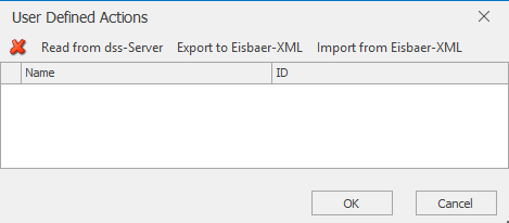
Custom Actions |
0 |
In this Window, the custom actions can be imported. |
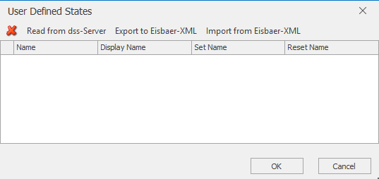
Custom States |
0 |
In this Window, the custom states can be imported. |
System states |
0 |
System states can be created in this window. Commands can be sent directly to the digitalSTROM server as text. |
Server [IP] |
|
Set the Server's IP address here. When Using the device name, it should be noted that it must not contain Blanks. |
Port [No.] |
8080 |
Set the Server's communications port here. Default is "8080." |
Login |
dssadmin |
Username to Access the Server. Default of the "dssadmin" server. |
Password |
********* |
User'S Password to Access the Server. |
Accept all certificates |
|
Connection security is not yet guaranteed for older servers. In this case, all types of certificates must be allowed in order to gain access to the device. |
Timeout [ms] |
15000 |
If there Is no Response to the Server, the Communication will be canceled after this Time. |
Read Device values at Start (Bus Query, slow) |
|
When the Project is started, all The values of the Device are read out. This Process is time-consuming. |
Sensor Update Interval (Bus Query, slow) [min] |
0 |
In the set Time Interval, the current sensor values (selected in the Channel editor) are read out of the Device (0 = disabled). As this is done via the Bus, the individual Queries take a very long time. This Option should only be used if reading out of the Server is not enough. |
Meter Update Interval (Bus Query, slow) [min] |
0 |
In the set Time Interval, the current meter values (selected in the Channel editor) are read out of the Device (0 = disabled). As this is done via the Bus, the individual Queries take a very long time. This Option should only be used if reading out of the Server is not enough. |
Sensor/Meter update Interval (Server request) [s] |
30 |
In the set Time Interval, the current consumption values of the Devices are read out of the Server (0 = disabled). |
Read out Unknown Scene values (Bus Query, slow) |
|
To read the associated values when Receiving Called scenes, if they are not already known. |
Cyclically update Scene-values |
|
To update scene values daily at the set Time. |
Cyclically Update scene values-Time (Hour) |
2 |
Setting the Time (0-23) to Update scene values |
Convert sensor Values |
Selected |
The Raw Data from the Sensor is automatically converted. For the Conversion, see the Conversion List below. |
Reset scene status only with "Undo" |
|
If active, the individual scene data points are only reset if they are canceled via "UndoScene" ("False" on the corresponding scene input). Otherwise, they are reset when another scene is called up. |
Reflect scene call |
|
If active, the status is output on the bidirectional scene data point. |
Create data points for individual scenes |
|
This option is used to create the individual scenes in addition to the general scene data points. |
Create device-specific data points for individual scenes |
|
This option is used to create the individual scenes for each device in addition to the general scene data points. |
Driver An/Aus |
|
Here, the Driver An/Aus is switched. |
Channels
Import the projected Data from the digitalSTROM server or from a polar bear XML to the Channel List. Finally, when You leave the Editor with OK, the existing Data Points will appear in the Dynamic Folder in the Data point window. It May be necessary to share the Polar Bear's access in the Web Interface of the Digital Power server.

Custom Actions/States
If actions And/or States have been created On the digitalSTROM Website, they can be imported here.
Conversion List:
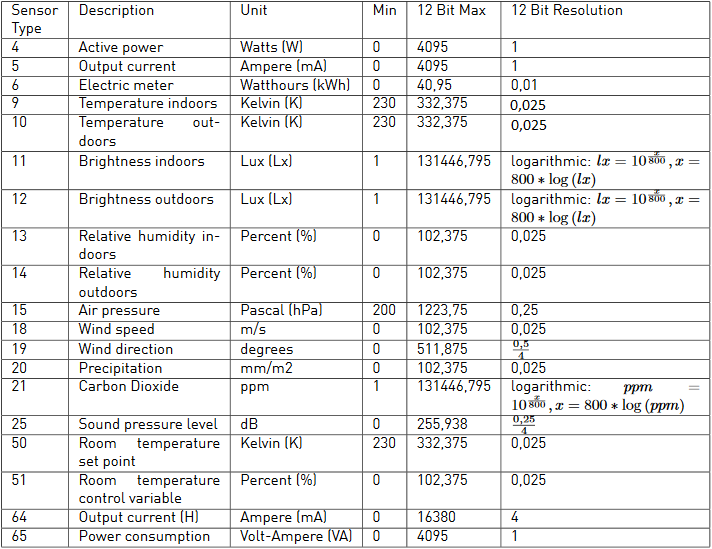
Excerpt from the digitalStrom Base concept Of the 19.08.2015
Further Links:
digitalSTROM System Documentaries: https://www.digitalstrom.com/technische-dokumentation/