General Information
Please note that only variables created in the system configuration of the WAGO controller can be imported by Codesys (only these are exported by Codesys to the CSV). Any variables created manually in the various programming languages are not included here.
CAUTION! If complex modules (such as the 0753-0646 KNX module) are installed in the WAGO system, make sure that they are integrated after the other input/output modules. The reason for this is that, if necessary, only one byte output variable is specified, but several (in this example 12) consecutive registers are actually reserved. This would move the following terminals in the address range correspondingly further back than the one byte specified in the CSV file.
If terminals are not inserted at the end, a new WAGO PFC driver must be used in the polar bear. Since the insertion of terminals changes the sequence and address structure and thus destroys the data points in the polar bear driver.
To transfer the networks from the old WAGO PFC driver to the new WAGO PFC driver, select the new WAGO PFC driver in the right part of the communication window. In the left window, select the old WAGO PFC driver. Then transfer the networks from left to right using drag and drop. Finally, the old WAGO PFC driver must be deleted.
Properties
Name |
Standard |
function |
|---|---|---|
Controller Type |
WAGO Ethernet 750-8xx |
Combobox for selecting the WAGO type. Currently devices of the series 750-8xx and 750-82xx are supported. |
Channels |
0 |
In the channel editor, the variables defined in the WAGO controller and, if necessary, physical inputs / outputs (750-8xx only) are imported. |
IP Address |
127.0.0.1 |
IP address of the WAGO controller. |
Port |
502 |
Modbus port of the WAGO controller. |
Timeout [ms] |
5000 |
Timeout for communication with the controller. |
Cyclic ping-check |
|
Activates the cyclic ping check (output of the accessibility on the corresponding data point). |
Cyclic ping-check Intervall [s] |
|
Interval of the cyclic ping check. |
Mode |
TCP |
Selection of Modbus mode. |
Temporary close connection |
|
Ends the connection after each poll (use only if required by the controller - usually not necessary for WAGO systems) |
Cyclic request - Delay [s] |
5 |
Pause between polling cycles in seconds. |
Cyclic request - Autostart |
|
Starts the cyclic query when activating the component. |
Cyclic sending - Delay [s] |
30 |
Pause between transmission cycles in seconds. |
Cyclic sending - Autostart |
|
Starts the cyclical transmission of all variables when activating the component. |
Send on value change |
active |
Sends a value changed in the polar bear individually and directly to the controller. |
Use old library |
|
This property can be set to use an older communication type. |
Driver On/Off |
|
Enables / disables the driver. |
Channels
In the channel editor, the variables defined in the WAGO controller and, if necessary, physical inputs / outputs (750-8xx only) are imported.
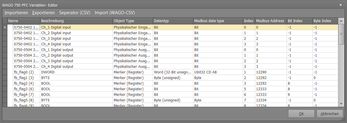
Abbildung : Properties - Variablenimport
In the option "Seperator (CSV)" the separator of the CSV file can be specified (Default,; '). The "Import (WAGO-CSV)" button opens the dialog for selecting a system configuration created using CODESYS for import.
The "Import" and "Export" buttons are only for exporting the channels currently imported / configured in the channel editor.
The table shows the name, the description and the object type (physical input / output (register), physical input / output (digital), PFC-in variables, PFC-out variables, flag variables). Furthermore, the WAGO data type is displayed. The associated Modbus data type is also pre-assigned, but can be adjusted if necessary (if a controller uses a different encoding for the 16/32 and 64-bit data types).
The index column reflects the number of the variable within its object type. The Modbus address displays the calculated Modbus address.
Bit index and byte index are only relevant for 1-bit and 8-bit variables and indicate the respective position within the 16-bit register.
Data points of the component
Name |
Type |
function |
|---|---|---|
Single request |
Input |
Triggers a one-time query of the data |
Cyclic request |
Bidirectional |
An on / off command can be used to start / stop the cyclic polling. |
Cyclic request - Delay [s] |
Bidirectional |
Here the cycle time of the query can be set. |
Diagnosis |
Output |
The diagnostic information is displayed there, linked to the [Signal] input of the log window. |
Dynamic |
Folder |
Contains the imported data points |
Ping state |
Output |
Outputs an on signal if the ping check was successful. |
Send on value change |
Bidirectional |
An on / off command can be used to switch transmission on value change on / off. |
Single send |
Input |
Triggers a one-time transmission of the data |
Cyclic send |
Bidirectional |
An on / off command can be used to start / stop the cyclical transmission. |
Cyclic send - Delay [s] |
Bidirectional |
Here the cycle time of the transmission can be set. |
Driver On/Off |
Bidirectional |
Driver on or off. |
Driver state |
Output |
Status display for the driver |
In the folder for Dynamice Datapoints a subfolder is created for each variable.
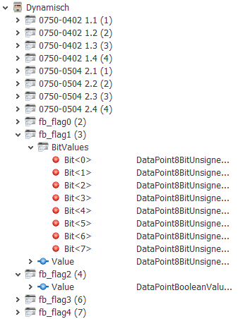
Depending on the variable type, this is an input, output or bidirectional data point. For UINT values, the individual bits are also created in a separate subfolder (outputs only).