The Z-Wave driver is an invisible server component and is used to connect to the Fibaro Home Center. All Z-Wave components must be learned and configured in the bridge.
Data points of the component
Name |
Type |
Function |
|---|---|---|
Disarm Alarm |
Input |
A string that corresponds to the PIN, which is stored in the FIBA ROHO MECÉ International, the alarm can be turned off for all devices. |
Arm Alarm |
Input |
About any command, the alarm is turned on for all devices |
Update all |
Input |
This data point is triggered, it sets the status of all devices are polled. |
Debug |
Output |
Here, error messages are output. This may, for example, be associated with the component " "Log window willbe displayed. Caution: Diagnostic or debug outputs are only in the event of failure. Please use only with consultation with the support team! This can significantly affect the performance of the service when using |
Event Messages |
Output |
The event messages are output as text. For example, the change in temperature or the like. |
Device state |
Output |
The output of the device states are connected |
Sent messages |
Output |
The output of the query commands from the FIBARO. |
Driver On/Off |
Bidirectional |
Drivers on or off. |
Connection State |
Output |
Are the result of the last availability check. |
Properties of the component
Name |
Standard |
Function |
|---|---|---|
Connection settings |
FIBARO ... |
Opens the editor to configure the gateway. Currently, the Fibaro Home Center as a Z-Wave Gateway supports. This is the IP address, as well as user name, password, and communication timeout. |
Devices |
0 |
Opens the editor to import the devices. From the Z-Wave Gateway, the devices are imported and in accordance with the hierarchy in the list. It is important to note that a ZWave device from one entry for the device itself and underlying components. The names are completely by the gateway; and, if necessary, there should have already been fully and meaningfully be named (in the case of the fibaro gateway corresponds to the name of the ID by default). In addition to the number of Sub-Kanale Gerate-Id is also displayed. This information is only relevant for Switch (so-called Central Scene Controller) and provides information about the number of buttons. |
Scenes |
0 |
Opens the editor to import the scenes. You can see the scenes, the scene number as well as the name of the scene assigned room number is imported and displayed. |
Rooms |
0 |
Opens the editor to import the rooms. It shows the name of room, the room number as well as the number assigned to the room019999 imported and displayed. |
Sections |
0 |
Opens the editor to import the sections. The section name and the section number is imported and displayed. |
Update interval [s] |
10 |
Here you can set up the intervals by setting the status of all devices (in addition to the independent running explicitly queried event check). |
Event check interval [s] |
2 |
Here, you can enter the interval set by the |
Driver On/Off |
|
This can be used to set whether the component at the start of the system should be active. |
In the folder for dynamic PLC are subfolders for general gateway information (Info and power plant). "Areas" within the folder are subfolders for designated areas and including if necessary for the designated rooms.
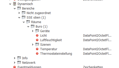
Figure : Shared properties - Dynamic
In the folder "scenes" you will find a further folder for the defined scenes and including two inputs to enter and exit of scenes, as well as an output that is triggered each time when the scene is called.
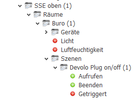
Figure : Shared properties - Scenes
Below the "Devices" folder is another folder per device. There are different depending on the type of PLC hereunder.
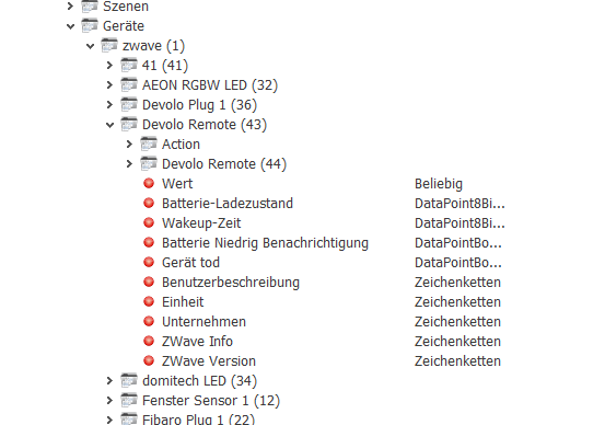
Figure : Shared properties - Equipment
If the device from other components (normal case), these are in corresponding subfolders to find, in accordance with the naming of the components are named. In the case of devices and components is at the end of the name of the respective ID number in parentheses.
Below the Components folder will be created in turn typ-spezifische plc. These are always outputs and provide information. In the "Action" folders folder below the device and component type-specific actions can be triggers. The available actions are transmitted from the Gateway.
Note: It is part of the specific device depends on whether the PLC values. For example, it is depending on the device, regardless of whether the current battery status on the device specific SP or one of its sub-components is transferred via the corresponding SP.
Note: Some of the actions require multiple parameters. This is realized by that there are several PLC of the corresponding name exists (with a number at the end). Here it is implemented in such a way that the PLC must be described in turn. The command is triggered when the last parameter is described. The exact meaning of the respective parameter is very device-specific and in the specific case to research.
Note: In the case of switches, several subfolders for each button. In each subfolder there are PLC for "pressed", "held" and "let go". It is the respective device dependent, which the PLC at a certain button is triggered. So, in the case of a manufacturer the PLC in the Folders Key1 and Key3 and Key5 and Key7, with another manufacturer is the assignment in turn completely different. This needs to be said here in the specific case must be examined individually and be linked accordingly.
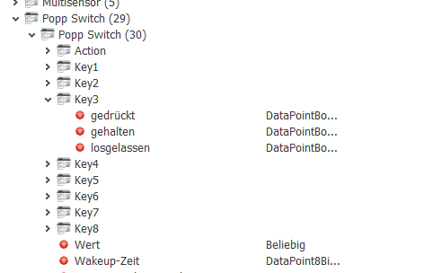
Figure : Shared properties - Multi-switch