To operate the CAN bus gateways, the corresponding driver must be installed.
Properties of the component
Name |
|
Function |
|---|---|---|
Messages |
0 |
Here the messages to be sent and received are defined. |
CAN Device |
IXXAT |
Currently, the IXXAT converters are supported (tested with USB-to-CAN, USB-to-CAN V2, USB-to-CAN Professional, CAN @ net II Ethernet Gateway). |
BAUD Rate |
10kBit/s |
Here, the BAUD rate is set. If the rate set here does not match the other devices on the bus, no communication is possible and bus errors may be generated. |
Frame Format |
|
In addition to the baud rate, the frame format is the second important feature that can be set globally. Here are the two options 11-bit (standard) and 29-bit (Extended) possible. All messages defined in the channel list use this identifier format. |
Driver On/Off |
x |
Driver on or off. |
CAN converter
Opens the editor for selecting the CAN converter
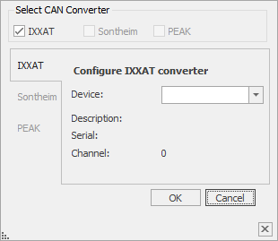
Abbildung : Properties - CAN-Umsetzer
The combo box displays all recognized (connected) adapters. If there are several ports on an adapter (such as USB-to-CAN Professional), an entry is created for each channel (channel number in brackets). In addition to the name of the device, its serial number and channel number are also displayed.
messages
The channel editor defines the messages to be sent and received.
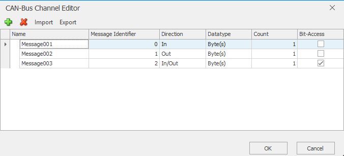
Abbildung : Properties - Nachrichteneditor
First, the message identifier (there should be only one transmitter for an ID bus-wide) and the direction (output = write on bus, input = receive from bus, bidirectional) are given.
The data type determines the encoding of the messages. Thus, for all data types that comprise more than one byte, the usual byte orders are selectable.
If byte is selected as the data type, then it is still possible to specify how many bytes (up to 8) belong to the message.
Ultimately, it can be defined per channel whether a separate SP should be created for each bit in order to gain direct access to individual bits.
Data points of the component
Name |
Type |
function |
|---|---|---|
Debug |
Output |
Error texts are output here. These may e.g. with the "Log window" component. The diagnostic information is displayed there, linked to the [Signal] input of the log window. |
Debug - Messages |
Output |
Here all sent and received messages are output. These may e.g. with the "Log window" component. The diagnostic information is displayed there, linked to the [Signal] input of the log window. |
Dynamic |
Folder |
The Folder Dynamic displays the input and output channels. Depending on the type, different data points are provided. The channels are created in the properties window. |
Driver On/Off |
Bidirectional |
An on signal activates the driver. The default state of the driver from the properties is output at the start of the simulation or the server. |
Driver State |
Output |
If the connection to the Modbus gateway is successful, an on signal is output. |
Normally, there are one or two SPs for each message. An SP via which a message can be sent (Bidirectional or Output) or output (Bidirectional or Input) and optionally (for inputs and Bidirectional messages) an input to explicitly request the message over the bus (RequestFrame).
For messages with activated bit access, a subfolder with the SPs for the individual bits (number depends on the selected data type) is also created. If several bytes have been specified for messages of the type Byte, a subfolder with an SP for the ByteValue On is created for each of the bytes. If additional bit access is activated, there is another subfolder with the associated bits for each byte. For outputs (or bidirectional) with multi-byte and bit-access, the message is sent whenever a change is made to one of the associated SPs.
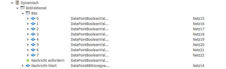
Abbildung : SharedProperties - Bitzugriff