Please take the time to read the section Important Notes before proceeding with the design.
First steps in EisBaer
Start Editor and create solution
After starting the editor a project folder need to be created in the first step. There are three options:
Use the key combination Ctrl + N, or use the buttons (A, B)
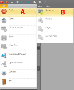
The EisBaer solution wizard opens, which leads you through the creating of a new solution.
1.Define solution name
2.Name the project
3.Add project (currently only one project per solution)
4.Add and name the first page
5.Optional: resolution / format of the page can be defined
6.Add page(s)
7.Close wizard
Now you see the actual work space of the editor with the currently created page.
Add and configure KNX-Driver
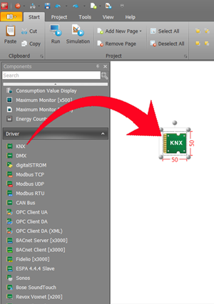
The first step is to insert a KNX driver on the page by drag & drop from the list of components (left side) to enable communication. To do this, click on the component with the left mouse button and drag it onto the desktop (middle field). Release the mouse button to insert the component at the location.
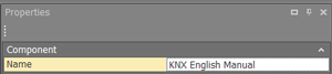
On the right side are the properties of the component, as well as the driver data points list.
Each component should be given a unique name to keep track of larger projects. Otherwise, the driver can be left at the default settings.
To get the data points of the KNX driver, the ETS project has to be imported. By clicking on the field Datapoint list (1) the import dialog opens.
Depending on requirements, the required import dialog can be opened here (ETS4, ETS5, ETS6). See also: Setting up the KNX driver
1.Select import format / ETS version
2.Select project file (eg * .knxproj)
3.Select project
4.To confirm
5.Result window is displayed
6.To confirm
7.Now the data point list contains all data points contained in the project.
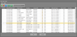
If required, the data points or read flags can be adjusted. First and foremost, however, this should always be done in the ETS in order not to overwrite the changes in a further import and to fundamentally minimize the error sources. Always consider the ETS software as the basis - both for your KNX system and your visualization projects.
If the data point types were not set in the ETS:
Unclearly defined data types are indicated by the red question mark in the first column. When importing, the ETS only outputs the data width of a group address if the data point type was not defined. Different types of data have different possibilities of interpretation. Right-clicking on the question mark opens a selection of the possible data types. Select the desired data type and the question mark disappears.
Note: When importing the data EisBaer automatically selects the "common" data types to save you this work. So it is usually only necessary to make these adjustments when you z. B. with 2-byte measured values, date, time or counter measurement data work. In these cases, follow the instructions of the manufacturer in the manual of the device. As a rule, the required data type is specified there.
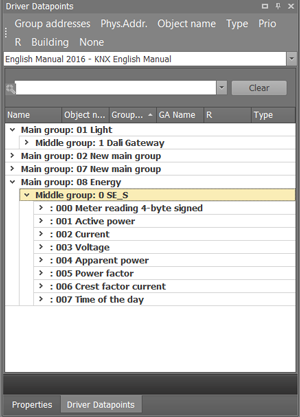
Data points in the group address view. In the header of the window the sort by group addresses can be activated .
Add and configure a button control
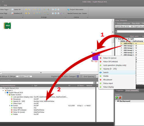
If a control element is inserted, it can be linked to a group address. Drag and drop the desired group address either directly onto the button (1) or onto the data point window (2) of the component .
Now these two data points are linked via an automatically generated network. In the communication window of the component one can see the linked group address and network.
Save the project and start the simulation mode.
Internal links
By highlighting the first component the data points will be displayed in the communication window. Linking is carried out by drag&drop of the data point from the communication window to the target component. If you drag the desired data point onto the target component a window open up and shows all available data points of the target component. Drop onto the desired target data point. It automatically creates a network with a unique number.
Start project in server mode
Open Server Configuratione Console
1.Select IP address, if the default IP 127.0.0.1 is set, it works exclusively with the client on the same computer. Another choice is the IP address of the computer/server, it is advisable to assign a fixed IP it will be always clear on what address the server can be reached.
2.Select solution and project
3.If no hardware license exists, you can install the license, or plug in the USB license dongle into the server PC.
4.In order to launch the project effectively, the server has to be stopped and started again. (After each change of the solution, this step must be performed to activate the changes in the server).
5.Wait for server feedback of load state of the project and validility of the license.
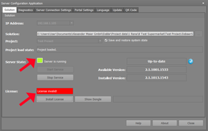
Important: After each change of the solution, this step must be performed to activate the changes in the server
Connect Client
Start the Client
1.When starting the client, it tries to establish a connection to the EisBaer server. If this does not work, a red bar is displayed at the bottom of the client window. The client tries up to 40 times to connect to the server. The connection attempt can be aborted at any time.
2.Open the server search window via "File" - "Open
3. Use "Search Server" to find possible servers in the network. After a few seconds the available server(s) will be displayed.
4.With "Add Server" the server can be added manually via the IP.
5.Check the Autostart box of the desired server and confirm with Connect.
6.Optionally, another server can be added as a "slave" to create a redundant system.
7.If necessary, change the user name and enter the password if these have been changed in the editor.
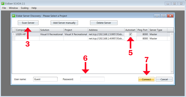
Upon successful completion of these steps, the project is ready.