This invisible driver component is intended for connecting the Siemens LOGO! 8.FS4. The PLC communicates via the network using the Modbus TCP protocol. LOGO! software V8.1 or higher is required.
Data points of the component
Name |
Type |
Function |
|---|---|---|
Unique query |
Input |
Have an on/Aus-Flanke at this input is a unique query of values is triggered. |
Cyclically query |
Bidirectional |
Here is whether or not the Cyclic query output is active. The Cyclic query about an OFF signal is deactivated. With an ON signal is activated. |
Query cyclically - break [s] |
Bidirectional |
Here is the set interval between two queries. An integer value is sent to the data point changes the pause time accordingly. This is, for example, with a touch input value possible. |
Diagnostics [Text] |
Output |
Here, error messages are output. This may, for example, be associated with the component " "Log window willbe displayed. Caution: Diagnostic or debug outputs are only in the event of failure. Please use only with consultation with the support team! This can significantly affect the performance when using the service. |
Ping status |
Output |
Here is an ON signal is output when the last ping check is successful. |
Dynamically |
Folder |
In the Folder dynamically, the input and output channels are displayed. Depending on the type, different data points provided. The number is defined in the Properties window. |
Once send |
Input |
Have an on/Aus-Flanke at this input is a unique send the values is triggered. |
Send a value change |
Bidirectional |
If this data point, it is a true until the LOGO! Sent when a value changes. |
Send cyclically |
Bidirectional |
Spend here is whether or not the cyclic sending is active. The cyclic sending over an OFF signal is deactivated. With an ON signal is activated. |
Send cyclically - break [s] |
Bidirectional |
Here is the set interval time between 2 send telegrams. An integer value is sent to the data point changes the pause time accordingly. This is, for example, with a touch input value possible. |
Driver On/Off |
Bidirectional |
The driver is activated via an ON signal. The default state of the driver from the properties of the server at the start of the simulation or output. |
Driver Status |
Output |
If the connection is successful, the Modbus Gateway is an ON signal is output. |
Properties of the component
Name |
Standard |
Function |
|---|---|---|
IP address |
127.0.0.1 |
This is the IP address of the LOGO! Module. |
Device ID |
0 |
Registration of the device ID |
Port |
502 |
This is the port address of the LOGO! Module Set. The default address is 502. |
Timeout [ms] |
5000 |
After a time, the query is waiting for a response. Then an error message will be displayed. |
Cyclic Ping Check |
|
If there is an interruption in the connection after the "Ping Check Interval" time, an error message is output. |
Ping Check interval [s] |
30 |
Cycle time for the connection test (Ping Check). There are 1-30 seconds. |
Query cyclically - break [s] |
5 |
Cycle time of the queries. The default setting of "5" is started every 5 seconds a query of all values. |
Query cyclically - Auto Start |
X |
This is the automatic start of the queries is activated. The queries then restart automatically at simulation start in the editor and when starting the server. |
Send cyclically - break [s] |
30 |
Cycle time of sending. The default setting of "30" appears every 30 seconds started sending all values. |
Send cyclically - Auto Start |
|
This is the automatic option is selected. Sending then starts automatically when you start the server and at simulation start in the editor. |
Send a value change |
X |
This selection is set, we directly on the LOGO! Sent when an input value changes. |
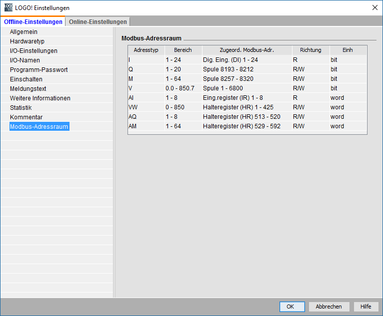
Number of digital inputs (I) |
24 |
Set the number of digital inputs that are to be used in the project. |
Number of digital outputs (Q) |
20 |
Set the number of digital outputs, which are to be used in the project. |
Number of digital memory (M) |
64 |
Set the number of digital markers, which are to be used in the project. |
Number of variable digital memory (V) |
2000 |
Set the number of variables, the digital markers are to be used in the project. |
Number of analog inputs (AI) |
8 |
Set the number of analog inputs to be used in the project. |
Number of analog outputs (AQ) |
8 |
Set the number of analog outputs that are to be used in the project. |
Number of analog memory (AM) |
64 |
Set the number of analog markers, which are to be used in the project. |
Number of variable analog flag (VW) |
425 |
Set the number of variables, the analog markers are to be used in the project. |
Use old library |
|
This property can be set to use an older communication type. |
Driver On/Off |
X |
Drivers on or off. |
Configuration of the LOGO!
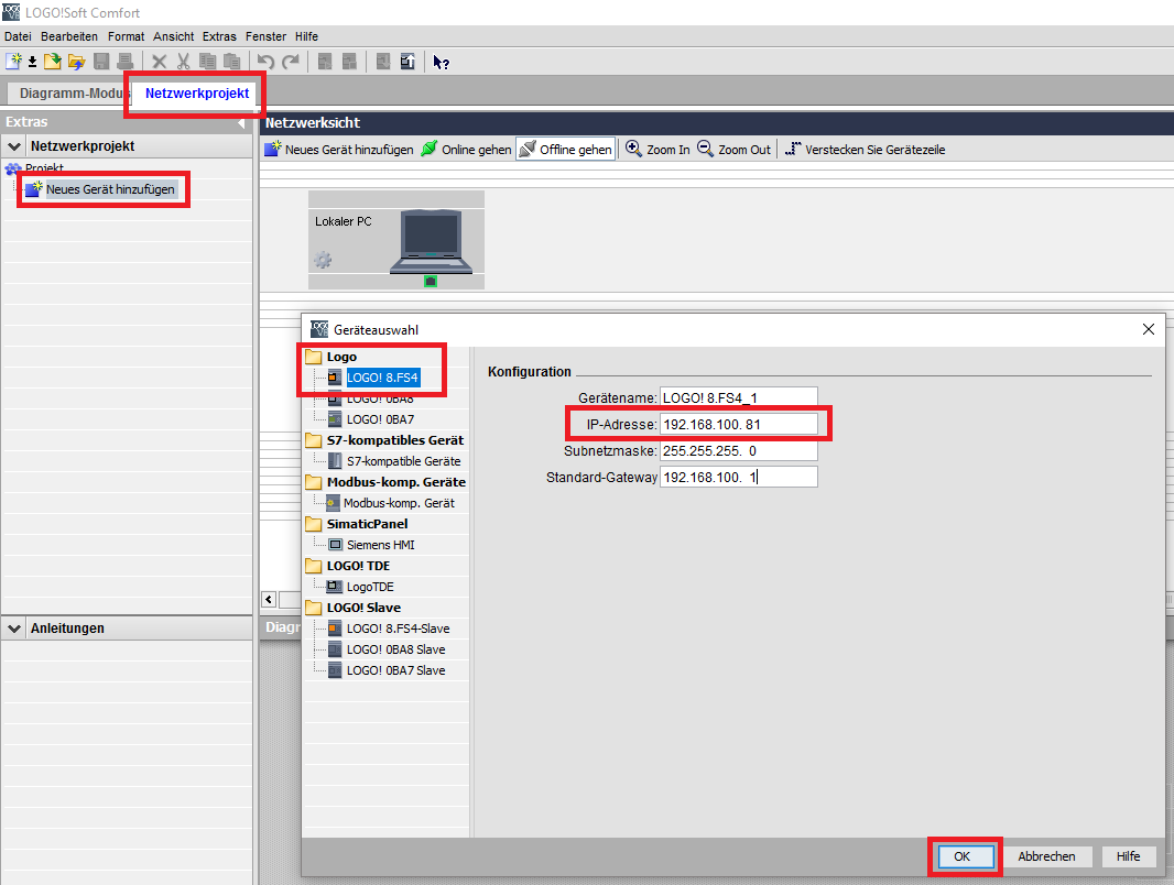
In the Siemens LOGO!Soft Comfort software is first to integrate the logo itself. In the tab "power plant project" is about a double-click the device selection will be opened. In the selection of the LOGO! 8.FS4 must be the correct IP address / Standard gateway of the PLC can be set. (Setting of the device in accordance with the manual p. 70/71 and p. 110/111). The entry is confirmed with "OK".
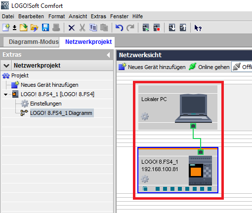
After confirming the connection in the "Power Plant Project" - view is displayed.
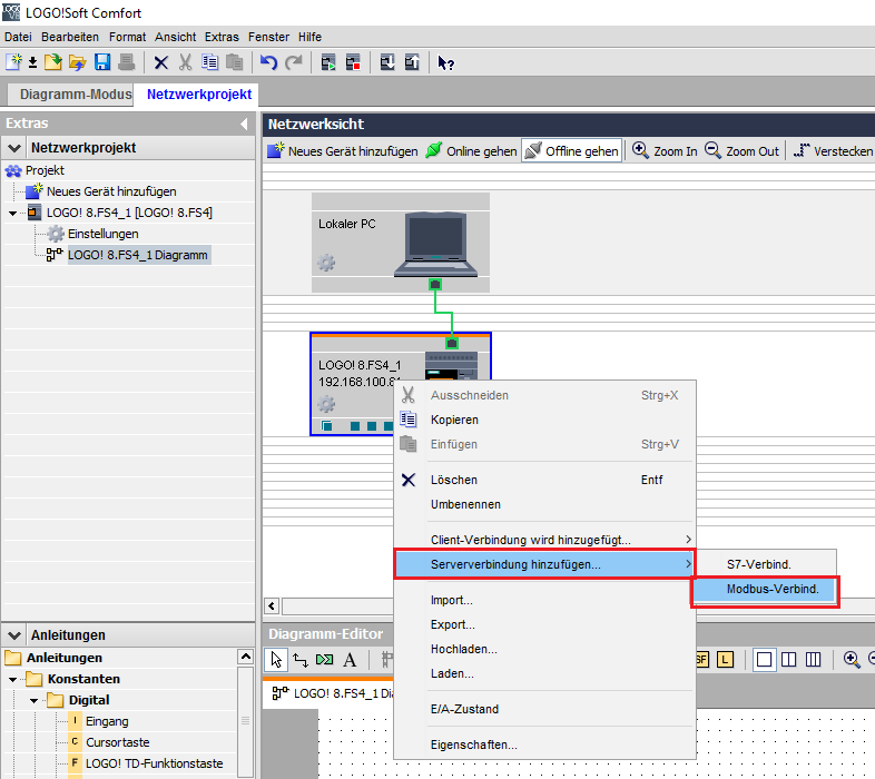
In order to enable the Modbus connection via a right-click on the LOGO! In the selection "Add connection" and "Modbus Server Connect." The interface is inserted.
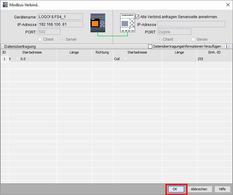
In the window that opens, then there is no need to entries are made. With a confirmation by clicking "OK", the connection is added.
In the "Power Plant Project" - view is now on the LOGO! A yellow ┴ is displayed. The project must then be in the LOGO! Transferred and in the RUN mode.
For manual input, a double-click on the yellow icon to return to the Connection view.
Important:
The logo project must be edited below from this link. Not in the "Chart Mode" tab! The diagram should be gray, this editor by double-clicking on the logo is enabled.
_ _
_