The fault message manager is an unVisiblee server component for recording fault and operational messages. For each message a good range can be defined. If the signal leaves the good range, a fault is triggered. For centralized signaling of the fault situation, collective outputs in accordance with DIN 19235 are available as new value message. In addition, fault conditions can be signaled by e-mail.
The course of the disturbances is stored in an internal database. Each manager has its own database.
The component is not visible on the interface in the client.
To use the fault message manager, at least one fault message manager display, as a visible client component, must be connected.
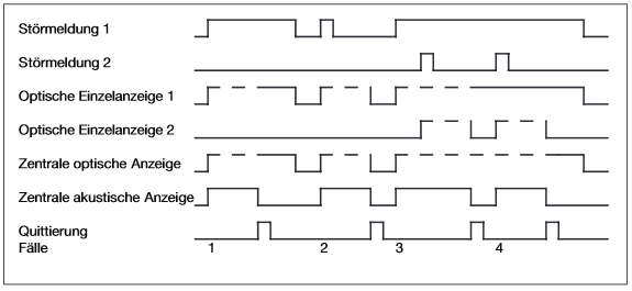
Flowchart of messages:
Data points of the component
Name |
Type |
function |
|---|---|---|
Active Alarms [Text] |
Output |
Outputs a text that includes all Active Interference |
Number of active messages [High priority] |
Output |
Outputs the number of active messages of the corresponding priority. |
Number of active messages [Info] |
Output |
Outputs the number of active messages of the corresponding priority. |
Number of active messages [Medium priority] Output |
Output |
Outputs the number of active messages of the corresponding priority. |
Number of active messages [Low priority] |
Output |
Outputs the number of active messages of the corresponding priority. |
Dynamic (Display after channels have been defined) |
Folder |
In the Dynamic folder there are further folders in which the created channel can be wired according to the designation. -Deactivate: The individual fault messages can be deactivated with an ON signal. -Individual acknowledgement: An individual acknowledgement input is available for each fault message. -Message input: The inputs for the defined messages are displayed. -Opticalindividual display: The fault message status of each individual alarm message is output. Alarm triggered: alternating on/off every second Alarm terminated: alternating on/off every second Alarm confirmed: off Confirmation before alarm ended: on Confirmed alarm ended: off
ATTENTION: After starting the programme, the outputs are only set in the event of a fault. The state of a connected component is undefined in the good state. |
Mail Debug |
Output |
When using e-mail signaling, diagnostic messages relating to e-mail transmission are output here. The diagnostic information is displayed there, linked to the [Signal] input of the log window. |
External notification |
Output |
This data point can be linked to the SMS or PUSH component to forward messages (see below). |
Last Event [Text] |
Output |
Returns a text that contains the last error |
Summary Deactivation |
Input |
An on signal at this input deactivates all messages in the tab. |
Summary Alarm |
Output |
See "Output Concept" below. |
Summary Alarm Confirmation |
Input |
An on-signal at this input acknowledges all messages in the Active tab. |
Summary Alarm Alert |
Output |
See "Output Concept" below. |
Summary Alarm (high priority) |
Output |
See "Output Concept" below. |
Summary Alarm (info) |
Output |
See "Output Concept" below. |
Summary Alarm (medium priority) |
Output |
See "Output Concept" below. |
Summary Alarm (low priority) |
Output |
See "Output Concept" below. |
SMTP Account User |
Input |
Here you can change the user name for the outgoing mail server. |
SMTP Account Password |
Input |
Here you can change the password for the outgoing mail server. |
Faultmanager Display |
Bidirectional |
Connection between a fault message manager and one or more fault message manager displays. |
Collective Alarm (high priority) |
Output |
See "Output Concept" below. |
Collective Alarm (info) |
Output |
See "Output Concept" below. |
Collective Alarm (medium priority) |
Output |
See "Output Concept" below. |
Collective Alarm (low priority) |
Output |
See "Output Concept" below. |
Properties of the component
Name |
Default value |
Function |
|---|---|---|
Channels |
0 |
Here the individual messages are defined in a list. These then appear as inputs in the data point folder Dynamic. Subfolders can be created with #, whereby the text before # is the folder name and the text after # is the data point name. This allows data points to be summarised. Example: Current#L1; Current#L2; Current#L3 - A Current folder containing the data points L1; L2; L3 appears in the Dynamic folder. |
E-mail Settings |
|
The settings of the mail server for sending e-mails are made here. |
Encoding |
System Default |
Setting option for the character set to be used: UTF8, UTF7, UTF32, Unicode (UTF16), System Default (e.g. ISO-8859-1), Unicode big endian (UTF16BE) and ASCII. |
Channel / Meldung definieren
Columns marked with an asterisk (*) can be edited simultaneously using the multi-select function.
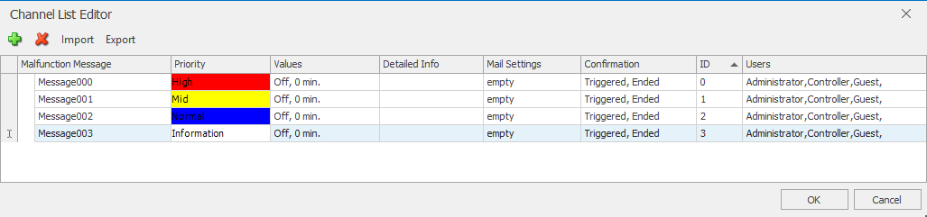
Add a message:
Error message:
Name of the message with up to 255 characters, this is also the name of the data point at the fault manager (Folder Dynamic).
Priority:
Here you can choose from High (RED), Medium (YELLOW), Low (BLUE) or Information (WHITE). See explanation of the color scheme below.
Allowed values:
Here, the value range for the good status of a message is defined. There are two types of values possible, Boolean and any values. For any values, the good value range is defined by a start and end value.
Cyclic monitoring in min. (0-360): Cyclic monitoring can be activated for each message. If 0 is specified, this function is not active. If the value is greater than 0, the input of the message is monitored and a fault is triggered in the event of a signal failure. If no signal is received within the specified time, a fault is also triggered. To ensure that no fault is triggered, a good message must be cyclically sent to the fault message manager.
Error details (info button):
A detailed text for the message can be entered here via an editor and/or a hyperlink can be called up. Files but also URLs are possible as links, e.g. pdf documents or network cameras can be called up directly from the detailed text.
Calling up files also works in the WebApp. For this, an http path must be used as the file link. A web server is integrated in the polar bear server for this purpose.
The files must be stored in the following memory path on the polar bear server:
C:\ProgramData\Alexander Maier GmbH\EisBaer 3.0\www\DATEINAME
e.g. C:\ProgramData\Alexander Maier GmbH\EisBaer 3.0\www\Delta.pdf
The retrieval link in the EisBaer fault message manager must be set as follows:
http://IP-ADRESSE:8003/Eisbaer.RESTServices/CustomWebsite/DATEINAME
e.g. http://192.168.100.11:8003/Eisbaer.RESTServices/CustomWebsite/Delta.pdf
E-mail settings:
Here you define one or more e-mail addresses to which a message is automatically sent. The e-mail contains the trigger time (date/time of the message), the name of the message and the message status as the subject. As message content, the fault details are transmitted as text, hyperlink incl. linked external documents. It is defined which of the message states should trigger an automatic e-mail. In order to use the e-mail service, thee-mail datamust be entered intheproperties of the component .An e-mail must also be entered for the "To address".
External notification:
If faults are to be forwardedto the PUSH or SMScomponent , a pseudo e-mail must be entered for the "To Address"
The correct, service-dependent recipient ID is entered before the @.
After the @ follows "local." (incl. the dot) followed by the service identifier:
•eisbaer
Empfänger-ID@local.eisbaer
Ex: QXg2vOyMqICaJkm2sdfr66474e520EWvWXTg@local.eisbaer
•pushover
Empfänger-ID@local.pushover
Ex: uuno78tooCxwiqokfws6rwVMHFQ6nH@local.pushover
•prowl
Empfänger-ID@local.prowl - the recipient ID is the API key from the prowl account.
Bsp: 523ac413d8b83509fae8f253185a275bf47@local.prowl
•redone
Empfänger-ID@local.redone
Ex: Sanitaeter + Betrisbsschutz@local.redone
•sms
Nummer@local.sms
Ex: 0170123456789@local.sms
acknowledgment:
Under History, you can select which message states must be acknowledged: Fault triggered and/or Fault completed. This defines whether a message is displayed in the "New" tab when the corresponding state is reached. In addition, under "Logging behaviour" it is defined whether the name of the logged-in user is logged or whether an input field with name/password for an authentication of the user pops up (free).
Export exports all channels in XML format.
Import imports channels from an XML file.
ATTENTION: The existing channels are replaced with the imported channels. Channels that no longer exist are deleted and linked networks are lost. Newly added channels are not automatically linked.
Color scheme:
Depending on the status, different colors are defined for the messages:
- RED (high): dangerous condition, highest priority, immediate intervention required
- YELLOW (mean): abnormal condition, medium priority
- BLUE: Intervene expedient, lowest priority
- WHITE: neutral, information
- GREEN: normal state, intended for the above messages as "good state"
Edition concept:
Sequence: Alarm triggered / terminated / confirmed / confirmation before the alarm has ended / ended
Priority |
Collective visual indicator |
Collective visual indicators total |
Priority collective visual indicators |
Summary annunciator |
|---|---|---|---|---|
High |
on / on / off / off / - |
blink / blink / off / on / off |
blink / blink / off / on / off |
on / off / - / - / off |
Mid |
on / on / off / off / - |
blink / blink / off / on / off |
blink / blink / off / on / off |
on / off / - / - / off |
Low |
on / on / off / off / - |
blink / blink / off / on / off |
blink / blink / off / on / off |
on / off / - / - / off |
Information |
- |
- |
blink / blink / off / on / off |
on / off / - / - / off |