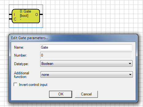
A Gate has one input, one output and one control input. The gate sends the value of an event at the input to output, when the control input is true. If the control input is false, nothing will pass from the
input to the output. The input also has a supplementary function. This defines the behavior of the gate, depending on the state of the control input.
Additional function
none |
If selected "none", the first received input value, after opening the gate, passes to the output. |
save during lock |
Selecting "save during lock", the last input value before opening the gate, is send to the output, when opening the gate. |
value buffer with send trigger |
Selecting "value buffer with send trigger", sends the output with each release command to the control input, even if the gate was already released and the input value has not changed. |
The input of the gate can be linked with an input object or an output of another component. The output of a gate can be connected to an output, or to an input of another component. A gate output
can be connected with several gate inputs.
The input is marked with an I and is located on the left side of the element. The control input is marked with an C and is located bottom on the left side of the element. The
Control input is invertible. This may be made within the parameter window or by double-clicking the S-connection.
The output is marked by an O, top right of the element. The name of the gate can be chosen freely.
Note: For input and output, all data types are allowed. For the control input are just 1-bit objects (Boolean) allowed.