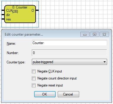
The counter counts the rising edges or pulses at the CLK input. With an input the count direction
(up/down) is selected. A reset sets the output value to 0.
In the "pulse-triggered-mode ", the counter output is increased / decreased by 1 when an entire pulse
(rising and falling edge) at the CLK input has been detected. In the edge-triggered-mode ", the counter output is increased / decreased by 1 when a rising edge (1-pulse) at the CLK input has been detected.
Using the control input DIR the counting direction of the counter is set. At no signal or 0 at the input,
it is counted upwards. A 1-signal sets the count-down-mode. In the "pulse-triggered-mode", the counter output is set to 0 if a complete Pulse (rising and falling edge) on the reset input RES was detected. On the CLK input is in principle then always a 1-signal. When you trigger the reset, this signal is not queried. The next arrival of the 1-signal at the CLK input starts counting again.
In the "edge-triggered-mode", the counter output is set to 0 with a rising Edge (1-pulse) at the reset input RES.
The counter counts in a circle, ie, when reaching the maximum is 32,767 is continued with -32,768. Opposite for the reverse count direction.
The inputs and the output can be inverted. This can be set within the parameter window, or by double-clicking on the connectors.
The inputs are marked with CLK, DIR and RES and are located on the left side of the element. The inputs are invertible. This may be made within the parameter window or by double-clicking the connection.
The output is marked by an O, top right of the element. The name of the gate can be chosen freely.
Note: The inputs are Boolean data types. The output data type is 2 bytes (Integer).