Using the "Maximum Monitor display" component for the control of the "Maximum Monitor". With an on/off signal at the data point "Visible" the component will be switched visible / invisible in
runtime. An on signal switches the component visible, an off signal invisible.
Note: Before you can use the "Maximum Monitor Editor" you must connect it with a "Maximum Monitor" component first.
Data points of the component
Name |
Type |
Function |
Lock operation (display only) |
Input |
If this input is not used, the component can be operated normally. If the input is connected with an on-signal, the component will be locked can not be operated. It only has display function. The locked state of a component is displayed, with a padlock sign on a slightly gray background. |
Mouseover |
Output |
Sends out an On signal, if you hover over the component with the mouse pointer. |
Input |
||
Visible |
Input |
If this input is not used, the component is always visible. The component can be made invisible with an off signal on this datapoint and visible with an on-signal on this data point. |
Maximum Monitor |
Bidirectional |
Data point to link Maximum monitor display and Maximum monitor component bidirectionally. |
Client-View
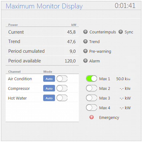
The elements / displays:
Designation |
Description |
|---|---|
Time indication |
Display of the remaining time until the next measuring cycle |
Currently measured power in kW |
|
Indication of the power expected at the end of the 15-minute interval. |
|
Accumulated period |
Indication of the average power over the entire 15-minute period. |
Period available |
Power value that can be drawn in the current period without exceeding the 15-min consumption limit. |
Work pulse |
Turns green when a work pulse or new value is received. |
Sync |
Turns green as soon as a sync pulse is received. |
Trend |
This indicator turns red as soon as the calculated trend exceeds the maximum setpoint. |
Prewarning |
This display turns red as soon as the set prewarning range has been reached. At the same time, a true is output at the maximum prewarning data point. |
Alarm |
This display turns red as soon as a failure of the counter signal or the synchronous pulse has been detected. |
Channel / Mode |
Display of the applied channels and their states at the output. Green = output for the channel is "ON", grey = "OFF". The mode can be changed from "Auto" (automatic load shedding active) to "Stop" (manual load shedding). |
Max 1 - Max 4 |
Indicates which tariff is currently active and the target power for this. |
Emergency operation |
Display turns red as soon as emergency operation has been activated. |