Excerpts from the M-Bus - Modbus-TCP Gateway User Guide
A detailed description is included with the device and is available in the download area on http://www.busbaer.de .
General
The M-Bus (Meter-Bus) is an established interface for automated meter reading. Above all, the simplicity of the installation (simple two-wire system with power supply through the bus) and the high degree of robustness distinguish it. These are special properties that are interesting for use in industrial environments.
The M-Bus is defined in the standard EN 13757. In addition to its own physics, it also defines its own protocol. For the connection to other systems a translation is necessary.
In the automation environment, Modbus TCP is widely used as a communication standard. With the products EisBaer TCP - M20 and EisBaer TCP - M80 (hereinafter referred to as EisBaer TCP - MBUS) two gateways are available which connect the world of the M - Bus with that of the Modbus TCP and thus the connection of meter data to ours EisBaer software enable.
The device supports the operation of 20 or 80 meters (standard loads) on the M-Bus side. For standard compliant data interpretation, a powerful protocol stack has been implemented on the EisBaer TCP - MBUS. With this it is possible, without further configuration effort, to read out all meters available on the market and to interpret their data. The data can be made available to other systems without any effort.
The EisBaer TCP - MBUS has an Ethernet interface that supports Modbus TCP in slave mode (Modbus TCP Server). As a Modbus master (Modbus TCP client), the EisBaer can directly retrieve the data of the counters via a network connection. These are available in Modbus registers.
Since the gateway EisBaer TCP - MBUS retrieves the counters autonomously, the initial configuration of the device is necessary. This is done intuitively via the configuration website of the device. Here is the full range of functions of the EisBaer TCP - MBUS Visible. In addition to the basic configuration, you can also select the values to be provided, perform bus scans and view the current data. Thus, the remote maintenance is facilitated via a service computer.
The EisBaer TCP - MBUS is supplied in a 2TE housing (graduation units) and is for the
DIN rail mounting (DIN rail 35mm) provided.
connection
The ports and interfaces of the EisBaer TCP - MBUS are routed out on different sides of the device.
The following pictures show the device:
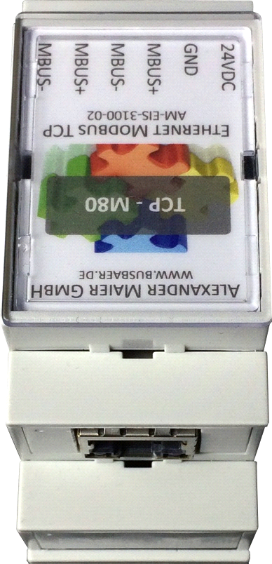
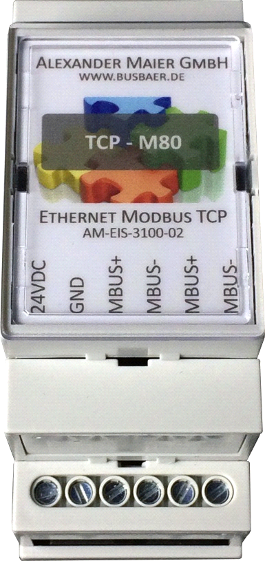
Figure: EISBAER TCP - M80
The following connections are available on the EISBAER TCP - MBUS:
connection |
Designation |
Pin Assignment |
Comment |
|---|---|---|---|
Voltage supply |
24VDC, GND |
24VDC: Positive connecting cable GND: Negative connecting cable |
24 VDC (±5%), Screw connecting cable 2,5mm² |
M-Bus-Connection |
MBUS+, MBUS- |
MBUS+: positive Bus-Cable (2x) MBUS-: negative Bus-Cable (2x) |
Screw connecting cable 2,5mm² MBUS+ und MBUS- are each connected to each other |
Ethernet-Connection |
Ethernet |
1: TX+ 2: TX- 3: RX+ 4: 5: 6: RX- 7: 8: |
as EIA/TIA-568A/B |
commissioning
The EisBaer TCP - MBUS starts automatically after connection to the supply voltage. By default, the following calls are made at system startup:
Configuration of the network interface (Ethernet) via DHCP or static configuration
Provision of the drive C: (RAMDrive) Relation of system time via SNTP
Start of the main program
The main program then presents the entire functionality u. a. The web interface of the EisBaer TCP - MBUS is available.
Network configuration and first access
The EisBaer TCP - MBUS is completely configurable via the network interface. This must therefore be configured according to your network. If necessary, ask your administrator.
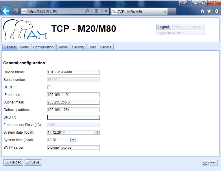
The EisBaer TCP - MBUS is set by default to the IP address 192.168.1.101 (subnet mask: 255.255.0.0, gateway: 192.168.1.254).
For intuitive operation, a configuration website is available on the device, which can be called up via the IP of the EisBaer TCP - MBUS in a browser.
Website on the EisBaer TCP - MBUS, z. B .: http://192.168.1.101/ The following page opens in the browser
configuration
The EisBaer TCP - MBUS is configured via the internal website. Alternatively, a configuration can also be manually created or transmitted based on the configuration files.
On the website, device parameters, meter configuration as well as service services can be displayed or changed.
Upon delivery, the website automatically logs in via the standard access data. If the standard user has already been deactivated in the configuration, the correct access data must be entered. To change an already logged in user (or standard user), the button Logout can be selected in the upper right corner.
The standard access data in the delivery state are included below.
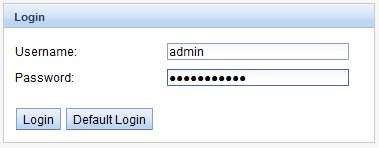
Figure 6: Login window
If the logged-in user has write access, it must be logged out again after the configuration has been completed. If the connection remains active, no other workstation can write to the EisBaer TCP - MBUS.
Tab General
The tab General shows a general overview of the EisBaer TCP - MBUS. The following values can be viewed or changed here:
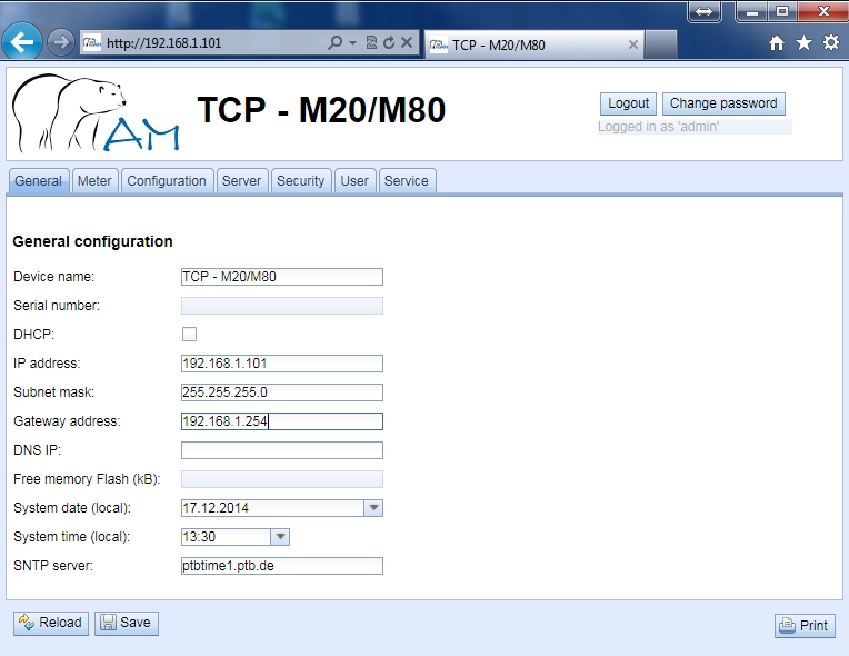
Fieldname |
Description |
write access |
Device name |
Name of the device (assignment in the CHIPtool) |
Yes |
Serial number |
Serial number of the device |
NO |
DHCP |
Enable automatic network configuration |
Yes |
IP address |
IP address of the device |
Yes |
Subnet mask |
Subnet mask of the device |
Yes |
Gateway address |
Gateway Address |
Yes |
DNS IP |
IP address of the DNS server * |
Yes |
Free Memory Flash (kB) |
Free space on the internal memory of the controller |
NO |
System date (local) |
Current, local system date |
Yes |
System time (local) |
Current, local system time |
Yes |
SNTP Server |
Address of the time server |
Yes |
* If the DNS server is detected via DHCP, it will not be displayed on the website.
The configuration is saved with the Save button. With Reload, the last saved values are loaded and current changes are reset.
If the network configuration is changed, the EisBaer TCP - MBUS is available after saving under the new IP. All existing connections will be logged separately or logged in users will be logged out automatically.
Changing the network parameters of the EisBaer TCP - MBUS can limit the accessibility. If the network parameters have already been set correctly by an administrator, they should not be changed.
By setting the parameters via the Save button, the ICEBAR becomes TCP MBUS
automatically reinitialized.
The date and time are always processed in UISBÄR TCP - MBUS as UTC time (without time zone shift). When displayed on the website, the browser converts them according to the locally set time zone of the computer. In Central Europe this is for example the Central European Time or the Central European Summer Time. If a different time zone is set here, the time on the website will be displayed accordingly.
Tab meter
The Meter tab shows an overview of the connected meters and gives the user the ability to automatically search for meters, manually add counters or configure existing meters:
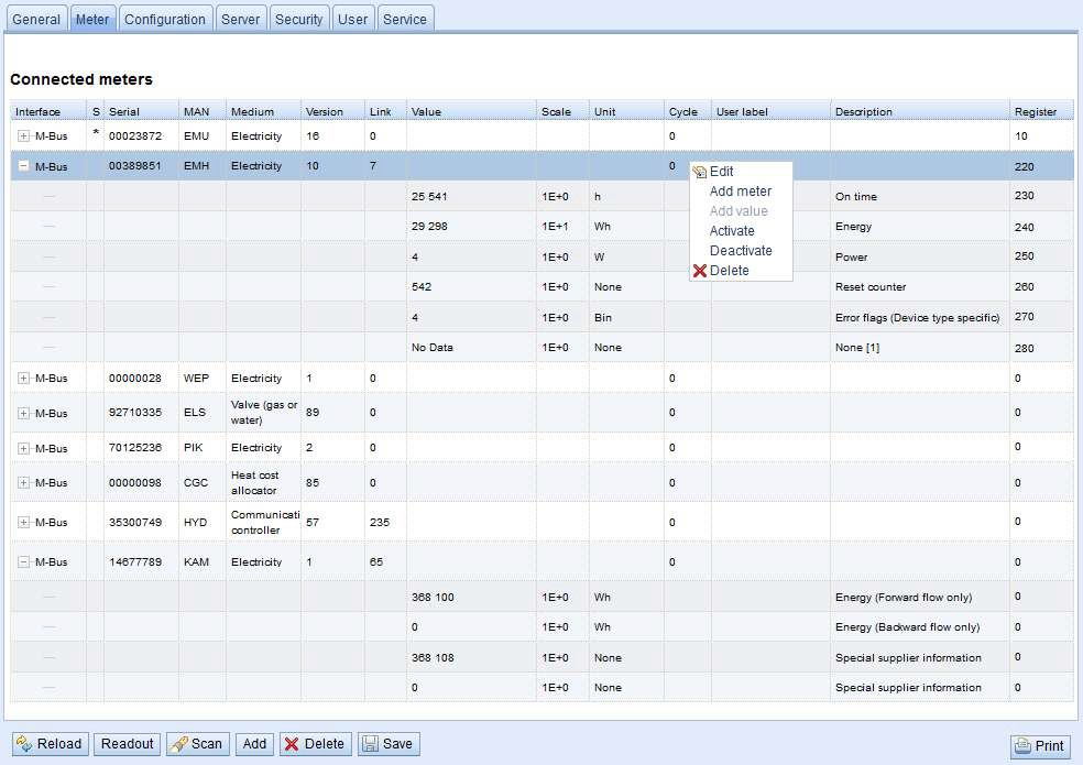
Field name |
Description |
Interface |
Interface to the meter (M-Bus) |
S (Status) |
Shows the status of the counter or counter value (exclamation mark: counter not readable or counter value not up-to-date, E: counter / counter value edited, A: counter / counter value newly added, asterisk: counter value list limited see parameter Maximum value count in tab Configuration) |
Serial |
Serial number of the meter (meter number, secondary ID) |
MAN |
Manufacturer of the meter (abbreviation) |
Medium |
counter medium |
Version |
Version number of the meter |
Link |
Primary address of a counter |
Value |
Meter reading or measured value |
Scale |
Scaling factor (scientific notation) |
Unit |
Unit |
Cycle |
Read-out interval in seconds (at 0 the general read-out cycle is used) |
User label |
User-defined description of the counter value - Permissible characters are: A-Z, a-z, 0-9,!, §, $,%, &, /, (,), =,?, + And * A comma is also permitted. Inadmissible are: <,> and ". |
Description |
Description of the counter value corresponding to the second column in Table 18: Measurement Types. The display of the memory number, tariff, value type and raw data can be configured via the parameter Description mode in the tab Configuration. |
Register |
Modbus register address with a fixed grid of 10 registers each. Counter values with the address 0 are not transmitted in the Modbus TCP protocol. |
Tab Server
The Server tab allows the parameterization of the Modbus interface of the EisBaer TCP - MBUS. The following
Parameters are available here:
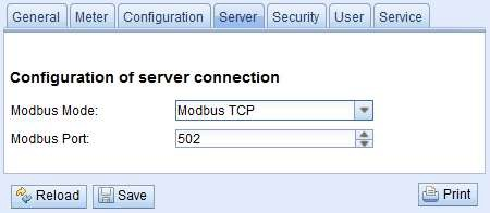
Field name |
Description |
Write access |
Modbus Mode |
Operating mode Modbus TCP |
No |
Modbus Port |
Network port to which the remote station (the Modbus TCP client) must connect |
Yes |
The configuration is saved via the Save button. With Reload, the last saved values are loaded and current changes are reset.
By setting the parameters via the Save button, the EisBaer TCP - MBUS is automatically reinitialized.
Tab User
In the tab User different users with specific access rights can be created. in the
As delivered, the following users are preconfigured:
User name |
Password |
Comment |
admin |
admin |
Administrative user who has full access to all services of the EisBaer TCP - MBUS (HTTP, FTP, Flash update, IP configuration) |
web |
web |
Standard user for the web interface - Is there a user with this name and password, The web interface automatically logs in with these access data. Otherwise, the user is prompted to enter the access data. Upon delivery, this user has full access to the website of the EisBaer TCP - MBUS |
ftp |
ftp |
User for FTP access to the log directory: C: / log |
Upon delivery, the EisBaer TCP - MBUS contains the three preconfigured users admin, web and ftp.
The user admin can not be changed or deleted in the general user configuration. The administrator password can only be changed via the Change password button if the user admin is logged in himself.
If the administrator password is lost, the EisBaer TCP - MBUS can only be reset at the company Alexander Maier GmbH. Access to the files on the EisBaer TCP - MBUS is limited. When resetting, all configuration data is lost.
Only the user admin has full access to the file system of the EisBaer TCP - MBUS via FTP. The second FTP user can access C: / log.
Specification Modbus TCP
The Modbus protocol was originally developed by the company Modicon (today Schneider Electric) for the traffic with their controllers. Data was transmitted in the form of 16-bit registers (integer format) or as status information in the form of data bytes. Over time, the protocol has been continuously expanded. Modbus TCP is a kind of it.
Modbus TCP is part of the IEC 61158 standard
A specification can be found at: http://www.modbus.org
The Modbus protocol is a single-master protocol. This master controls the entire transmission and monitors any timeouts that occur (no response from the addressed device). The connected devices may only send telegrams if requested by the master.
The EisBaer TCP - MBUS Gateway is a Modbus TCP server and therefore a Modbus TCP slave.
Modbus communication requires the establishment of a TCP connection between a client (eg: PC with EisBaer SCADA) and the server (EisBaer TCP - MBUS). For communication, the Modbus reserved TCP port from the Server configuration tab is used. This is configured by default to 502.
If there is a firewall between the server and the client, make sure that the configured TCP port is enabled.
functionscodes
The following functionscodes are supported by the EISBAER TCP - MBUS:
Code |
Name |
Description |
0x01 |
Read Coil |
Currently without function |
0x03 |
Read Holding Register |
Calling up the meter data |
0x05 |
Write Single Coil |
Currently without function |
0x06 |
Write Single Register |
Currently without function |
0x10 |
Write Multiple Register |
Currently without function |
0x0F |
Force Multiple Coil |
Currently without function |
0x2B |
Read Device Identification |
Retrieve device information with MEI = 0x0E |
The function codes marked with "without function" are answered with ILLEGAL DATA ADDRESS (0x02), all others not listed with the error message ILLEGAL FUNCTION (0x01).
If the functionscode 0x2B is used with MEI = 0x03, the device returns an identification packet. The values 0x01 and 0x02 are supported as Device ID code, so the basic device identification and the regular device identification data can be retrieved. The following data can be called up via the device identification:
Object ID |
Name |
Datatype |
Example |
Type |
0x00 |
VendorName |
String |
Alexander Maier GmbH |
Basic |
0x01 |
ProductCode |
String |
1036 |
Basic |
0x02 |
MajorMinorRevision |
String |
001 |
Basic |
0x03 |
VendorUrl |
String |
www.busbaer.de |
Regular |
0x04 |
ProductName |
String |
EisBaer TCP – M80* |
Regular |
0x05 |
ModelName |
String |
Standard |
Regular |
0x06 |
UserApplicationName |
String |
Modbus TCP Gateway |
Regular |
* Corresponds to the configured device name in the General tab
data arrangement
The data arrangement in the Modbus registers corresponds to the usual structure. The big endian representation is used, so in the 16-bit registers the higher byte is sent first, the lower one after that.
Example: Value: 0x1234 is sent: first 0x12, then 0x34
Numbers and data ranges exceeding 16 bits are represented similarly. Again, the most significant 16-bit register is sent first, so it is at the lowest register address.
Example: Value: 0x12345678 is sent: first 0x12, then 0x34, 0x56 and 0x78
The arrangement of the 32- and 64-bit values can be adjusted within the system configuration via the MODBUS_SWAP parameter.
To check the data layout, the transmission of pseudo data can be activated in the tab Server. The following data is then provided via Modbus according to the register assignment:
Address |
Value |
Description |
Decodet Value |
0 |
0x0002 |
Serial number of the EisBaer TCP – MBUS, upper Word |
0x2993A |
1 |
0x993A |
Serial number of the EisBaer TCP – MBUS, lower Word |
|
2 |
0x0001 |
Version of the communication protocol of the EisBaer TCP - MBUS |
1 |
3 |
0x006F |
Version of the Software of the EisBaer TCP – MBUS |
0x6F = 111: Version 1.11 |
4 |
0x519C |
time stamp of the EisBaer TCP – MBUS, upper Word |
0x519CC16D = 1369227629: Wednesday, 22. Mai 2013, 15:00:29 GMT+2 |
5 |
0xC16D |
time stamp of the EisBaer TCP – MBUS, lower Word |
|
6 |
0x0000 |
empty |
|
7 |
0x0100 |
Type field of the register file in the upper byte |
0x01: Gateway entry |
8 |
0x0000 |
empty |
|
9 |
0x0000 |
empty |
|
10 |
0x00BC |
Serial number of the counter, upper Word |
0xBC614E = 12345678 |
11 |
0x614E |
Serial number of the counter, lower Word |
|
12 |
0x0443 |
Manufacturer identification of the meter (see chapter: 6.2.2) |
0x0443: ABC |
13 |
0x0102 |
Version (upper Byte) and Medium (lower Byte) of the counter |
0x0102: Version 1, Medium 2 (electricity) |
14 |
0x519C |
time stamp of the counter, upper Word |
0x519CC164 = 1369227620: Wednesday, 22. May 2013, 15:00:20 GMT+2 |
15 |
0xC164 |
time stamp of the counter, lower Word |
|
16 |
0x0000 |
empty |
|
17 |
0x0200 |
Type field of the register file in the upper byte |
0x02: Counter entry |
18 |
0x0000 |
empty |
|
19 |
0x0000 |
empty |
|
20 |
0x0000 |
Counter value (integer), highest Word |
0xBC614E = 12345678 Resulting counter value: 12345678 * 10^-4 = 1234.5678 Wh |
21 |
0x0000 |
Counter value (integer) |
|
22 |
0x00BC |
Counter value (integer) |
|
23 |
0x614E |
Counter value (integer), lowest Word |
|
24 |
0x449A |
Counter value (floating point), upper Word |
0x449A522B = 1234.567800 |
25 |
0x522B |
Counter value (floating point)), lower Word |
|
26 |
0xFFFC |
Scale factor (Exponent to Basis 10) |
0xFFFC = -4: Factor = 10^-4 |
27 |
0x0005 |
Type field of the register file in the upper byte and unit in lower byte (see Section: 6.2.2 and Table 19: Units) |
0x00: Counter value entry 0x05: Wh |
28 |
0x519C |
time stamp of the counter value, upper Word |
0x519CBBB3 = 1369226163: Wednesday, 22. May 2013, 14:36:03 GMT+2 |
29 |
0xBBB3 |
time stamp of the counter value, lower Word |
Meter data acquisition and processing
The main task of the EISBAER TCP - MBUS is the processing and forwarding of the recorded counter values. For this, the following points must be fulfilled:
The available counters must be configured correctly in the EISBAER TCP - MBUS (counter configuration). For the transmission of data via Modbus TCP, valid register addresses must be configured for the individual counters or counter values.
The recorded meter data must be transmitted to a controller via Modbus TCP.
The meter data must be processed by the controller (meter data format).
Modbus register layout
This chapter describes the Modbus register specification. These work with a fixed grid of 10 Modbus registers each.
The register addresses are counted starting from the value 0.
For data types that include more than one register, the higher order data word is encoded at the lower address.
The Modbus registers are read out via the function code 0x03 (Read holding register).
In the Modbus protocol, the data is transmitted as an integer or float value. Other data formats that are specified for the M-Bus (e.g. BCD) are already converted internally into integer values before transmission. The 10 Modbus registers of a meter value entry are defined according to the following table, whereby the offset must be added to the configured Modbus address:
Offset |
designation |
data width |
Description |
0 - 3 |
count |
64 Bit |
Signed, integer counter value (unscaled) |
4 - 5 |
count |
32 Bit |
Floating point counter value (scaled to unit in register 7), IEEE 754 |
6 |
scaling factor |
16 Bit |
Signed scaling factor to base 10 |
7 |
Type field / unit |
16 Bit |
The type field (value 0 for counter value entry) is transferred in the higher-order byte. The unit is transmitted in the least significant byte. This is assigned using Table 19: Units in chapter 6.2.1. The transferred value corresponds to the index. |
8 - 9 |
time stamp |
32 Bit |
Unix-time stamp provided by the counter. If the counter does not transmit time values, this time stamp is 0. |
The following figure shows an example configuration of the Modbus addresses via the web interface:
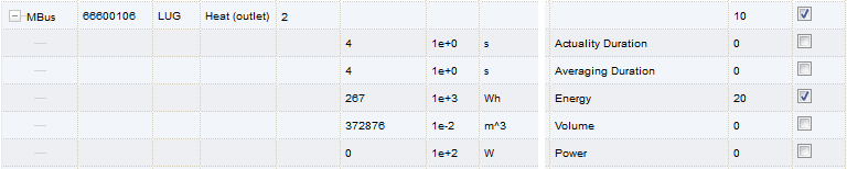
The following data is transmitted to the Modbus master in this example.
Address |
Value |
designation |
Decodet Value |
18 19 |
0x0000 0x0000 |
Reserved |
|
Counter value entry |
|||
20 21 22 23 |
0x0000 0x0000 0x0000 0x010B |
Counter value (integer) |
0x000000000000010B = 267 Resulting counter value: 267 * 10^3 Wh |
24 25 |
0x4882 0x5F00 |
Counter value (integer) |
0x48825F00 = 267000.000000 Wh |
26 |
0x0003 |
scaling factor |
Factor = 10^3 |
27 |
0x0005 |
Type field / unit |
Type = 0 → Counter value entry Unit = 5 → Wh |
28 29 |
0x519C 0xBBB3 |
time stamp |
0x519CBBB3 = 1369226163 = Wednesday, 22. May 2013, 14:36:03 GMT+2 |