The Modbus TCP driver is an unVisiblee server component with the possibility to connect Modbus gateways.
Specification Modbus TCP
The Modbus protocol was originally developed by the company Modicon (today Schneider Electric) for the traffic with their controllers. Data was transmitted in the form of 16-bit registers (integer format) or as status information in the form of data bytes. Over time, the protocol has been continuously expanded. Modbus TCP is another type of communication.
The Modbus protocol is a single-master protocol. This master controls the entire transmission and monitors any timeouts that occur (no response from the addressed device). The connected devices may only send telegrams if requested by the master.
Modbus TCP is part of the IEC 61158 standard. A specification can be found at: http://www.modbus.org.
Get supported:
Modbus RTU (Serial), ASCII (Serial),
TCP, RTU over TCP, ASCII over TCP und UDP-IP (also Secure).
Note: When reading out several devices, there is a 100ms time delay between 2 devices.
Data points of the component
Name |
Type |
Function |
|---|---|---|
Query cyclic - Autostart |
Bidirectional |
Here it is output whether the cyclic query is active. An off signal deactivates the cyclic query. Activated with an on signal. |
Cyclic query - Pause [s] |
Bidirectional |
The set pause time between 2 queries is output here. If an integer value is sent to the data point, the pause time changes accordingly. This is possible, for example, with a touch value input. |
Query once |
Input |
An ON signal at this input triggers a one-time query of the values. Each further on-signal triggers a further query. |
Updating is carried out |
Output |
An on signal is output at this output for the duration of the update. |
Diagnosis [Data] |
Output |
Output of the raw data for each read register. |
Diagnosis [Text] |
Output |
Error texts are output here. These can be displayed e.g. with the component "Protocol window" .Attention: Diagnostic or debug outputs are only intended for error cases. Please use only with consultation of the support team! If used, these can significantly affect the performance of the service. If several drivers are available, the displays can be switchedvia the debugger. |
Dynamic |
Folder |
The subfolders for unit, unit status, value and value (factor) are created in the Dynamic folder. Unit: Text from the "Unit" channel editor. Unitstatus: There are 3 data points per unit ID. Unit active for (de)activating the unit query, unit status for the output whether the unit can be read out (true) and unit warning, which outputs true if the query failed. Value: Data point for the created channel without offsetting with the factor. Value (factor): Data point for the created channel with offsetting of the factor. |
Extended diagnostics |
Input |
The diagnostic output is extended via an on signal at this input. Attention: Diagnostic or debug outputs are only intended for error cases. Please use only with consultation of the support team! If used, they can significantly affect the performance of the service. |
Faulty units |
Output |
Output of the unit ID as text that cannot be read out. |
At least one value outside the range |
Output |
If limits have been entered for a value in the channel editor and this value is exceeded or not reached, an ON signal is output at this data point. Corresponding information is also output at the diagnostic output. |
Ping Status |
Output |
In case of an IP connection, the connection of the device can be additionally checked via a ping check. An on signal shows if a connection exists. |
Write cycle is being performed |
Output |
An on signal is output during the write cycle. |
Write cycle time [ms] |
Output |
Output the time in milliseconds how long the write took. |
Send once |
Input |
An ON signal at this input triggers a one-time sending of the values. Each further ON signal triggers a further transmission. |
Send cyclically - Autostart |
Bidirectional |
This output shows whether cyclical transmission is active. An off signal deactivates cyclical transmission. Activated with an on signal. |
Cyclical transmission - pause [s] |
Bidirectional |
The set pause time between 2 transmit telegrams is output here. If an integer value is sent to the data point, the pause time changes accordingly. This is possible, for example, with a touch value input. |
Driver On/Off |
Bidirectional |
The driver is activated via an on signal. The preset state of the driver from the properties is output when the simulation or server is started. |
Driver Gateway - MQTT Client |
Bidirectional |
Bidirectional communication interface between Modbus Master and MQTT Client. See Driver Gateway. |
Driver Gateway - BACnet Server |
Bidirectional |
Bidirectionalcommunication interface between Modbus Master and BACnet Server. See Driver Gateway. |
Driver Gateway - File Logger |
Output |
This data point can be connected to theDateilogger. This will transfer all data from the Modbus directly to Dateilogger. |
Update time [ms] |
Output |
Outputs the time for a device update in milliseconds. |
Connection - COM Port |
Bidirectional |
Here the COM port of the driver can be changed at runtime. |
Connection - IP Address |
Bidirectional |
Here the IP address of the driver can be changed at runtime. |
Connection status |
Output |
If the connection to the Modbus gateway is successful, an on signal is output. |
Properties of the component
Name |
Default |
Function |
|---|---|---|
|
The imported or manually created channels are listed here. These then appear as subfolders in the data point folder Dynamic. The description of the Modbus channel editor follows below. |
|
Serial ... |
The connection type to the Modbus device is set here (Com + IP-Adress). |
|
... |
This is where you configure the Modbus connection options |
|
Driver On/Off |
|
Switch driver on or off. |
Examples
- Modbus TCP to M-Bus Connection
- Modbus TCP Wago 750 connection
In principle, it is possible to forward data from a Modbus master to a Modbus slave.
Here it is important that the two Modbus lines are clearly separated.
Here is a diagram to illustrate this:
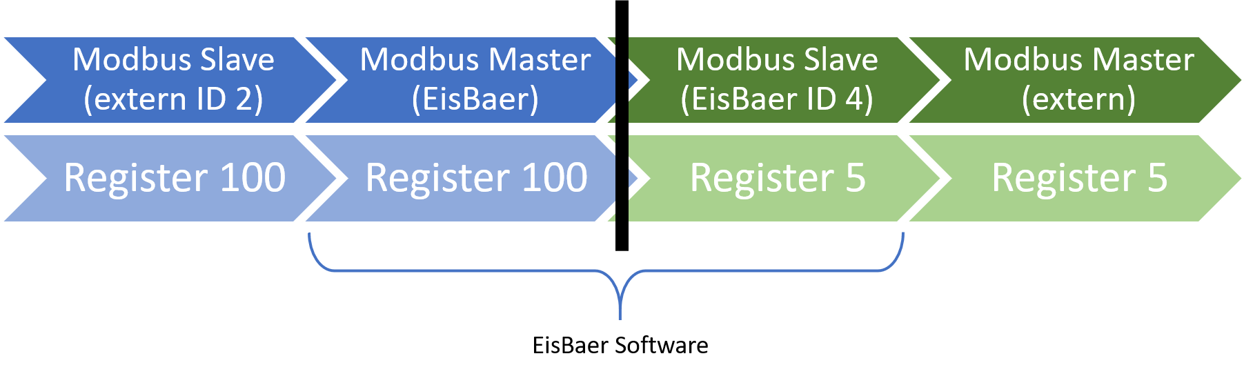
If a Modbus master is used in the EisBaer, the settings and registers in the instructions must be adopted from the Modbus slave.
If a Modbus slave is used in the EisBaer, you must check what the external Modbus master can do and which other slave devices are available on the Modbus line.
It is recommended that the device ID and the register addresses in the EisBaer slave are set uniquely.
This ensures that no two masters can access one slave. It also helps to better differentiate between the slave components.
In the diagram above, the black bar corresponds to the separation of the two systems. The data points of the driver components are linked 1:1.
Note on the TCP connection: in some cases the Modbus port 502 is blocked by the firewall.
Modbus in brief
A simple master/slave protocol (today also client/server): the master polls actively, the slave — the field device — answers.
Transport & addressing
- RTU and ASCII run over a serial line (RS-485, rarely RS-232), TCP and UDP over Ethernet/IP (port 502) — the content is identical, only the transport differs.
- RTU/ASCII over TCP or UDP: for serial servers / RS485-Ethernet gateways — the same framing, only the transport runs over the network instead of a COM port.
- Modbus/TCP Security: TCP connections can optionally be established TLS-encrypted.
- Unit ID: with RTU the unique device address 1–247, with TCP often 1 or 255.
- Register = 16 bits (one “word”). Larger values span several registers: 32-bit (Int32/Float32) = 2, 64-bit = 4 registers.
- Byte/word order: ABCD is the Modbus standard (big-endian); CDAB (word swap) is common on many PLCs for floats. Wrong order → nonsense values. The Decoder helps you find the right one.
The four data areas
- Coils (FC01): individual, writable bits — e.g. relays.
- Discrete Inputs (FC02): individual, read-only bits — e.g. switch states.
- Holding Registers (FC03): 16-bit registers, read & write — set points, parameters.
- Input Registers (FC04): 16-bit registers, read-only — measured values.
Funktionscodes
Function code |
Name |
Type |
Description |
|---|---|---|---|
FC01 |
Read Coils |
Read |
Read several coils (writable bits). |
FC02 |
Read Discrete Inputs |
Read |
Read several input bits (read-only). |
FC03 |
Read Holding Registers |
Read |
Read holding registers — the most common read code. |
FC04 |
Read Input Registers |
Read |
Read input registers (measured values). |
FC05 |
Write Single Coil |
Write |
Set or clear a single bit. |
FC06 |
Write Single Register |
Write |
Write a single 16-bit register. |
FC15 |
Write Multiple Coils |
Write |
Write several coils in one telegram. |
FC16 |
Write Multiple Registers |
Write |
Write several registers in one telegram — e.g. a 32-bit value across 2 registers. |
FC23 |
Read/Write Multiple |
Both |
ead and write in a single telegram (saves one round trip). |
FC43 |
Read Device Identification |
Read |
Read vendor, product name and version as plain text. |