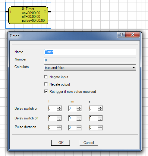
A timer can pass an event at the input with an on- or off-delay to the output. A pulse function can reset the output after a set period of time.
The input and the output can be inverted. This is possible within the parameter window, or through a double click on the connectors.
The input also has a supplementary function. With the "Calculate" parameter can be defined which event at the input is passed to the output (filter function).
Calculate
true and false |
On and Off signals at the input are used as trigger. |
only true |
Only an On signal at the input is evaluated. Off signals are filtered out, i.e. there is no calculation.. |
only false |
Only an Off signal at the input is evaluated. On signals are filtered out, i.e. there is no calculation. |
If the parameter "Retrigger if new value received" set, the time is retriggered and restarts from 0 again.
Delay switch on |
An on signal at the input of the timer is passed to the output after expiry of the set time. An off signal is, without delay, sent at the output. |
Delay switch off |
An off signal at the input of the timer is passed to the output after expiry of the set time. An on signal is, without delay, sent at the output. |
Pulse duration |
After an on signal at the input the output is turned on. After the set pulse duration time the output is turned off automatically. |
The input is marked with an I and, and is top left at the element. The output is characterized by an O, is top right of the element.
The name of the gate can be chosen freely.
Note: For the input and the output of the timer are just 1-bit objects (Boolean) allowed.